Home › Services › Flow Elements
Primary Flow Element Design
Orifice Plates · Venturi & Nozzle Meters · Cone & Wedge Meters · Restriction Orifices
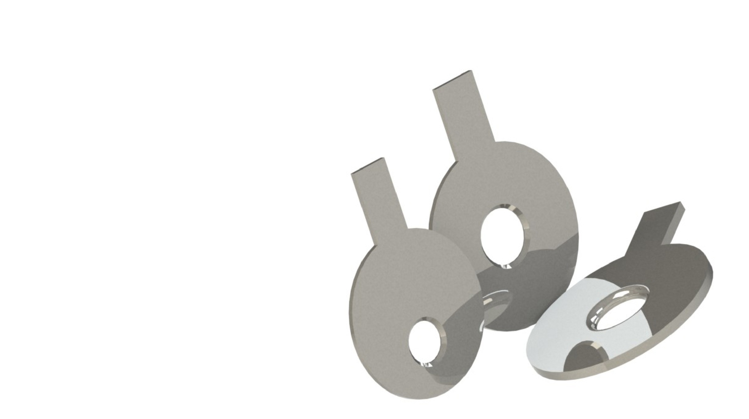
A flow element (also called a primary element) is a mechanical device installed directly in a pipeline that interacts with the flowing fluid to produce a measurable physical effect — typically a differential pressure, an area change, or a velocity profile — from which the flow rate can be calculated. Unlike electronic meters that rely on sensors and signal processing alone, flow elements are passive, purely mechanical devices: orifice plates, venturis, nozzles, cone meters, wedge meters, and pitot tubes being the most common types.
Because they generate a predictable, standards-based relationship between the physical effect and the flow rate, flow elements form the backbone of differential pressure (DP) flow measurement — one of the oldest and most trusted flow measurement principles in industrial use, and still the dominant technology in oil & gas, power, and process industries.
Common Flow Element Types
DP flow elements work on Bernoulli's principle, which states that for a fluid flowing through a pipe, an increase in velocity is accompanied by a corresponding decrease in static pressure, provided total energy along the flow path stays constant. By deliberately reducing the flow area — a bore, throat, or restriction — a flow element forces the fluid to accelerate, producing a measurable pressure drop between an upstream tapping and a tapping at or near the restriction. This differential pressure can then be related back to flow rate through a known geometric and physical relationship.
The general form of the DP flow rate equation, common to orifice plates, nozzles, venturis, and cone meters, is:
where Q is volumetric flow rate, C is the discharge coefficient, ε is the expansibility (expansion) factor for compressible fluids, d is the bore or throat diameter, ΔP is the measured differential pressure, ρ is fluid density, and β is the diameter ratio (d/D, where D is the upstream pipe diameter). The discharge coefficient C and expansibility factor ε are specific to each element geometry and are defined empirically in the applicable design standard.
Flow elements generate a differential pressure or velocity signal proportional to flow rate, enabling accurate, repeatable measurement of liquids, gases, and steam for custody transfer, process control, and mass balance applications across a wide range of pipe sizes and process conditions.
Restriction orifices and multi-stage RO assemblies are used purely for pressure and flow control rather than measurement — dropping pressure across a line in a controlled manner, limiting flow rate, and managing cavitation, choking, and noise in high pressure-drop applications.
Purely mechanical construction with no internal electronics, moving parts, or power requirement, resulting in high reliability and long service life even in harsh or remote environments.
Performance is predictable directly from published international standards without site calibration in many cases, since the discharge coefficient is derived from decades of empirical data.
Suitable for high temperature, high pressure, corrosive, erosive, and hazardous area applications where electronic sensors would require additional protection or would not survive.
No signal drift from electronic component ageing, minimal maintenance, and long-term cost advantages compared with meters requiring periodic electronic recalibration or replacement.
Fluid properties, flow range, pipe geometry, pressure, and temperature conditions are reviewed to establish the sizing basis and select the most suitable element type.
Bore, throat, or profile dimensions are calculated per the applicable standard, along with discharge coefficient, expansibility factor, and permanent pressure loss.
For non-standard, wet gas, or high turn-down applications, CFD simulation is used to validate flow behaviour, discharge coefficient, and pressure recovery beyond standard calculation limits.
A full measurement uncertainty budget is developed per GUM methodology, accounting for geometric, fluid property, and installation-related uncertainty contributions.
Many flow elements designed to recognised standards can be used without site calibration, since the discharge coefficient is already established from standard geometry. However, wet calibration is recommended, or required, for non-standard geometries, high-accuracy custody transfer applications, and elements operating outside standard Reynolds number or beta ratio limits.
Calibration is carried out on a traceable flow calibration rig against reference master meters, comparing the flow element's actual discharge coefficient with the value predicted by the applicable standard across the required flow range, and issuing a calibration certificate with a full uncertainty statement per ISO/IEC 17025.
Calibration Scope
Our design scope spans the full range of differential pressure and area-averaging primary elements, selected and sized to match your process conditions, accuracy requirements, and installation constraints.
All flow element designs and measurement solutions are developed in compliance with applicable national and international standards, ensuring traceability and acceptance in regulated and accredited environments.
| Flow Element | Governing Standards |
|---|---|
| Orifice Plate & Assemblies | ISO 5167-2, ASME MFC-3M, BS 1042, AGA-3 |
| Flow Nozzle | ISO 5167-3, ASME MFC-3M, BS 1042,ISO/TR 15377 |
| Venturi Tube | ISO 5167-4, BS 1042 |
| Venturi Nozzle | ISO 5167-3, ASME PTC 6 |
| Cone Meter | ISO 5167-5 |
| Wedge Meter | ISO 5167-6 |
| Averaging Pitot Tube | ASME MFC-12M |
| Restriction Orifice / Multi-Stage RO | ISO 5167, RW Miller Handbook |
| Wet Gas | ISO 11585, ISO 12748 |
For special and non-standard applications — including wet gas, multiphase flow, and high-turndown systems — we employ CFD simulation to design, validate, and optimise flow elements beyond the scope of standard calculations.
Technical Capabilities
Our experienced engineers will assess your system, identify the optimal flow element, and deliver a design that meets your accuracy, compliance, and operational requirements.
Discuss Your RequirementsCharacterises the discharge coefficient (Cd) and permanent pressure loss (PPL) orifice plate prototypes
Blog