Home › Services › Flow Elements › Wedge Meter
Wedge Meter Design
ISO 5167-6 · High Viscosity · Erosive & Slurry Service · 50 – 600 mm Lines
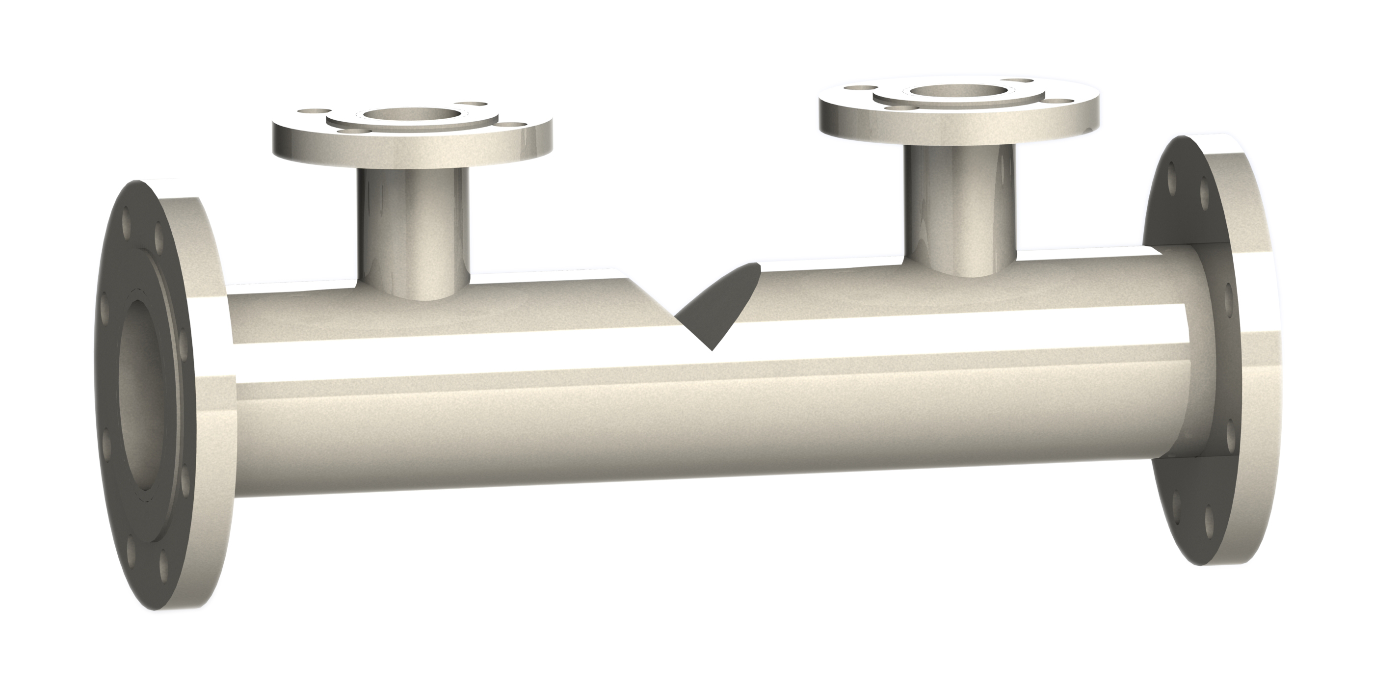
A wedge meter is a differential pressure flow element built around a V-shaped wedge fixed to the inside wall of a pipe section, with its apex pointing across the flow. The wedge leaves a segmental opening, which accelerates the fluid and produces a differential pressure between an upstream and a downstream pressure tapping. Both tappings sit on the same side of the body as the wedge.
ISO 5167-6:2022 sets out the geometry, installation and operating conditions of the wedge meter for single-phase, subsonic flow in a full circular conduit, and is applied together with ISO 5167-1. Because the restriction is a solid wedge rather than a thin sharp-edged bore, it is a practical choice for viscous, erosive, dirty and slurry fluids where an orifice plate would wear or plug.
The size of the wedge opening is described by the wedge ratio h/D, the gap between the apex and the pipe wall divided by the inlet diameter. This is related to the diameter ratio β through the segmental area, so h/D = 0.5 corresponds to β ≈ 0.707, and β = 0.5 corresponds to h/D ≈ 0.298.
Design Basis
An uncalibrated wedge meter may be used with the coefficient given in ISO 5167-6 only inside the limits below. Outside them, the discharge coefficient has to be established by flow calibration over the full Reynolds number range of operation.
| Pipe internal diameter, D | 50 mm ≤ D ≤ 600 mm |
|---|---|
| Diameter ratio, β | 0.377 ≤ β ≤ 0.791 |
| Wedge ratio, h/D | 0.2 ≤ h/D ≤ 0.6 |
| Pipe Reynolds number, ReD | 1 × 10⁴ ≤ ReD ≤ 9 × 10⁶ |
| Surface roughness, Ra | Less than 10⁻³ D |
| Flow condition | Single-phase, subsonic, non-pulsating, pipe running full |
Extreme values of D, β and ReD should not be combined, as the uncertainty may increase.
The standard fixes the main dimensions of the wedge and its tappings so that the published coefficient applies. The key requirements are summarised here.
Wedge plane angle of 90° ± 2°, upstream and downstream external angles of 135° ± 2°, and an apex radius of 1 mm or less along its full span.
Entrance and exit cylinders of at least 0.5D, with no measured diameter differing from the mean by more than 0.4 %. Measured internal diameter, not nominal, is used in calculations.
Centrelines located 1D ± 0.02D from the nearest point of the wedge. Pipe wall tappings are 4 – 10 mm; large bore branch tappings are 25 – 75 mm and never larger than D.
Weld beads are kept small and must not intrude into the throat area. Hollow wedges need a pressure equalisation system for structural stability under rapid pressure change.
A solid wedge keeps its shape in abrasive and erosive service far better than a thin-edged orifice plate.
Performs well in viscous service. A flow calibration allows operation over a wider Reynolds number range than the standard's uncalibrated limits.
The segmental opening lets entrained solids pass. Large bore tappings with diaphragm seals suit slurry, corrosive and fouling fluids.
With a Clause 7 calibration, discharge coefficient uncertainty becomes comparable to that of orifice, nozzle and Venturi devices.
Covered by ISO 5167-6, giving a documented method for flow calculation, uncertainty and installation.
Can be applied to reverse flow, provided tapping and thermowell positions are considered and calibration covers both directions.
Permanent loss follows a simple relation to the measured differential, reducing as β increases.
May be made from any material and construction method, provided the specified geometry is held in service.
An uncalibrated meter carries a 4 % coefficient uncertainty, relatively high compared with orifice, nozzle and Venturi devices.
Uncalibrated use is limited to 50 – 600 mm lines and ReD from 10⁴ to 9 × 10⁶. Beyond that, calibration is required.
Results apply to the individual meter and flow direction tested, cannot be extrapolated, and each set of tappings is treated as a separate meter.
Flow calculation is sensitive to the pipe diameter and wedge gap, so both must be measured accurately and entered correctly.
Upstream lengths are measured from the end of the curved part of the nearest fitting to the upstream tapping. The values below keep the shift in discharge coefficient within 0.5 %.
| Fitting upstream of meter | Minimum straight length |
|---|---|
| Single 90° bend | 7D |
| Two 90° bends in the same plane | 21D |
| Three 90° bends, parallel inlet and outlet | 22D |
| Concentric expander (D/2 to D) | 7D |
| Concentric reducer (3D/2 to D) | 7D |
| Partially closed valve | 15D |
| Pipe tee, straight run | 7D |
| Pipe tee, used as elbow or tee | 8D |
Fully open full-bore isolation valves add no extra error.
Fittings at least 6D downstream of the downstream tapping introduce no additional error.
The pipe must be cylindrical over the required upstream length and 6D downstream, with no diameter differing from D by more than 2 %, and roughness below 10⁻³ D.
A thermowell is best placed 4D to 14D downstream of the downstream tapping. Flow conditioners are generally not used with wedge meters.
Where lower uncertainty is needed, or the design lies outside the standard's geometry or limits, the standard calls for the meter to be flow calibrated. Calibration determines the discharge coefficient of the individual meter and its uncertainty.
Calibrate at least over the entire Reynolds number range expected in service, using liquid, gas, or both in separate tests. Extrapolation is not permitted.
The facility must give appropriate traceability for the application, with ISO/IEC 17025 as guidance on what is suitable.
At least 10D of straight inlet and 2D of outlet are used. If service piping differs significantly, it should be replicated at the test facility.
Reports give differential pressure, Reynolds number and discharge coefficient, with uncertainties at k = 2 evaluated by ISO 5168 or ISO/IEC Guide 98-3.
Summarised from ISO 5167-6:2022. Refer to the full standard for the complete requirements.
Our engineers will size a wedge meter to ISO 5167-6 for your fluid properties, line size and Reynolds number range, and plan the calibration if needed.
Discuss Your Requirements