Home › Services › Flow Elements › Aerofoil
Aerofoil Flow Element Design
Rectangular Ducts · Air & Gas · Minimal Pressure Loss · No Moving Parts
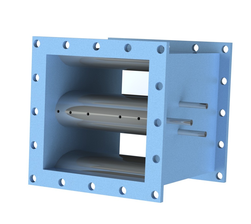
An aerofoil flow element is a differential pressure device built for square and rectangular ducts, where orifice plates, nozzles and Venturi tubes cannot be fitted. It is named for its wing-like cross-section: two or more streamlined foils span the duct, forming a smooth contraction that accelerates the gas and creates a measurable pressure difference.
Sensing ports are drilled along each foil and joined inside by a common manifold, so the pressures picked up across the duct width are averaged. Ports facing the oncoming flow supply the high-pressure signal; ports in the throat region supply the low-pressure signal. The resulting differential pressure is related to flow rate through the element's calibrated coefficient.
Because the profile guides the gas rather than blocking it, much of the pressure drop is recovered downstream. The permanent loss is therefore a small fraction of the measured differential, which matters in fan-driven systems such as boiler air and flue gas ducts, where every pascal costs energy.
Design Basis
Typically two foils with a smooth, rounded leading profile and a gradually widening tail, fabricated from plate to suit the duct section.
Drilled along the foil centreline facing the flow and linked to an internal collector pipe that averages the upstream pressure.
Located at the throat on the top and bottom surfaces of each foil and joined to a second internal collector for the low-pressure signal.
Supplied with end flanges for bolting into the duct, with both signal lines brought out for impulse tubing and transmitter connection.
The aerodynamic shape gives good pressure recovery, keeping fan power and operating cost down.
Needs far less upstream and downstream duct than most differential pressure devices, easing installation in congested plant.
With nothing to wear or adjust, routine maintenance is limited to checking impulse lines and ports.
Fits the duct shape directly, avoiding transition pieces to round pipe that other primary elements would require.
Suitable for gas carrying light dust loading, and less prone to erosion than sharp-edged restrictions.
Averaging ports across the duct produce a stable, repeatable differential pressure signal.
Flanged construction allows the element to be bolted in as a spool, and field installed in existing ducts where needed.
Carbon steel for typical air service, with stainless steel 304 or 316 or other grades for higher temperature or corrosive gas.
Typical uncertainty is a few percent, so it suits process and efficiency monitoring rather than custody transfer.
It is not covered by ISO 5167, so the discharge coefficient depends on the manufacturer's calibration or CFD data.
Generally applied to larger ducts, with 500 mm and above being typical; smaller sizes need special design.
Heavy dust or sticky deposits can foul sensing ports, so purging or periodic cleaning may be needed.
| Uncertainty | Typically 3 – 5 % |
|---|---|
| Rangeability | Up to about 10:1 |
| Beta ratio | Typically 0.32 – 0.59 |
| Permanent pressure loss | Typically below 20 % of measured ΔP |
| Straight length | As short as about 2D |
| Duct size | Typically 500 mm and above |
| Materials | Carbon steel, SS 304, SS 316, others on request |
| Connections | Flanged or field installed |
| Pressure taps | Threaded (NPT) or socket weld |
Figures are typical industry values for aerofoil elements. Actual performance is confirmed for each project during design.
Aerofoil elements are most often chosen where air or gas flows through large rectangular ducts and pressure loss, space for straight run, and installation effort all count against a conventional orifice or Venturi arrangement.
Our engineers will size and verify an aerofoil flow element for your duct dimensions, gas conditions and pressure-loss limits.
Discuss Your Requirements