Home › Services › Flow Elements › Orifice Plate
Orifice Plate & Assemblies
Concentric · Eccentric · Segmental · Multi-Hole · Carrier Ring Assemblies
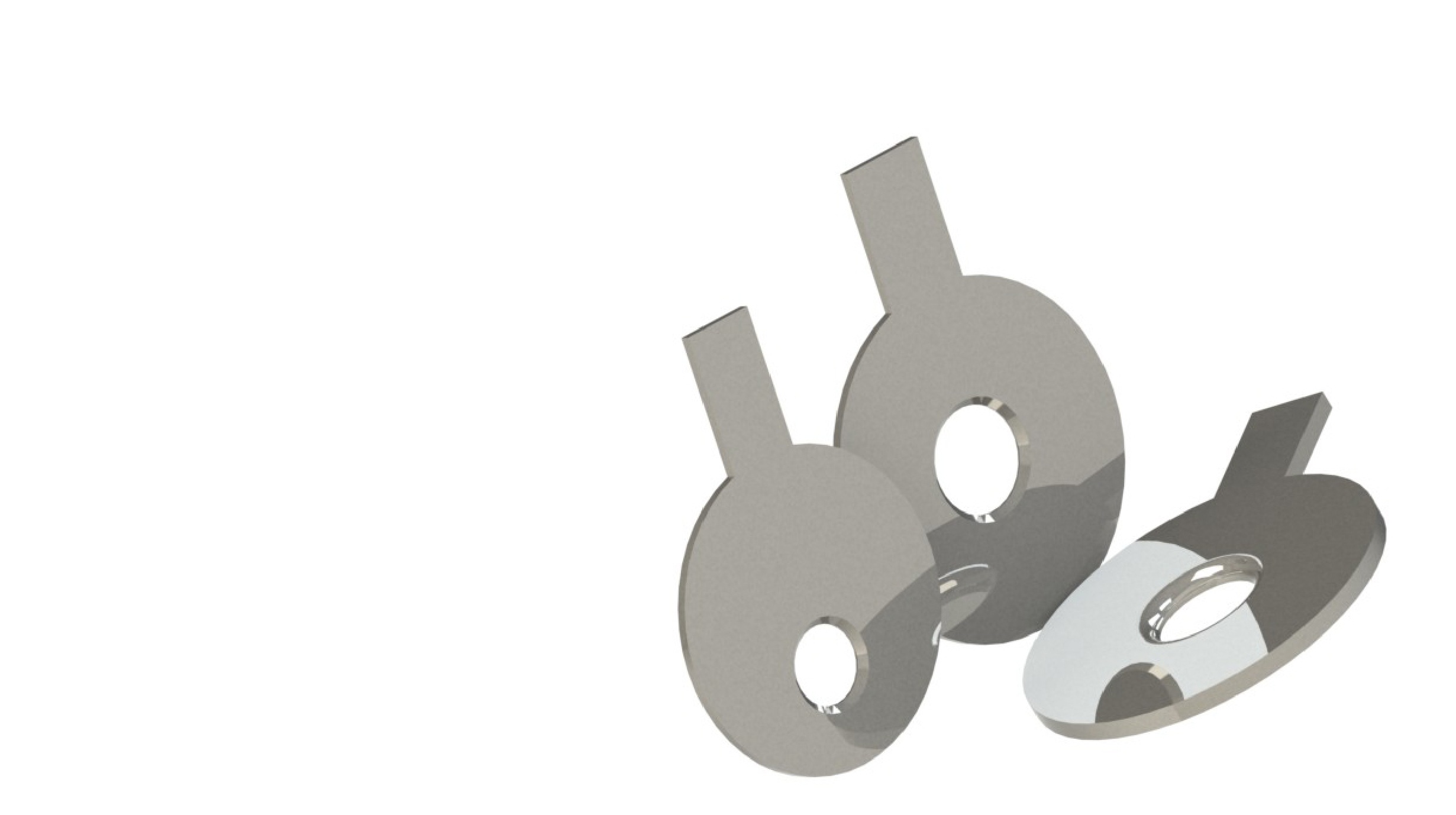
An orifice plate is a thin, precision-machined plate with a bore of known diameter, mounted concentrically or otherwise in a pipeline. As fluid passes through the reduced bore, it accelerates, and the resulting differential pressure between the upstream and downstream tappings is used to calculate flow rate. It remains the most widely used primary flow element in industry, owing to its simplicity, low cost, and the depth of standards-based data supporting its design.
A complete orifice assembly typically includes the plate itself, a carrier ring or plate holder for ease of installation and removal, orientation tabs for correct fitting, and tapping arrangements (flange, corner, or D and D/2) for connecting to the differential pressure transmitter.
Design Basis
The most common type, with a bore centred on the pipe axis. Suitable for clean, single-phase liquids and gases with well-developed flow profiles.
Bore offset toward the top or bottom of the pipe, used for fluids carrying entrained gas, vapour, or solids, allowing them to pass without accumulating near the plate.
A segment-shaped opening rather than a circular bore, used for dirty or two-phase fluids such as slurries or wet gas where debris needs an unobstructed path.
Rounded or conical bore entrance profiles used for low Reynolds number applications such as viscous fluids, where a sharp edge would be unreliable.
Multiple smaller bores arranged in a defined pattern instead of a single bore, offering reduced permanent pressure loss and improved performance in disturbed flow conditions.
Designed primarily for pressure and flow control rather than measurement, often used as single or multi-stage assemblies to manage large pressure drops.
Simple construction and low material requirement make orifice plates the most economical primary flow element to manufacture and install.
Extensively documented in ISO 5167-2, ASME MFC-3M and BS 1042, allowing use without site calibration within standard limits.
Carrier ring and flange-mounted designs allow the plate to be inspected, cleaned, or replaced without major pipework modification.
Applicable to liquids, gases, and steam, and adaptable to a broad range of pipe sizes, pressures, and temperatures with the right material selection.
Sharp-edged bores create more irrecoverable pressure loss than venturis or cone meters, which can be significant in energy-sensitive applications.
Typical usable flow turndown is around 3:1 to 5:1, narrower than cone or wedge meters, which can handle much wider flow ranges.
Erosive or abrasive service can round the bore's sharp edge over time, shifting the discharge coefficient and introducing measurement error if not inspected periodically.
Accuracy is sensitive to upstream disturbances, misalignment, and tapping condition, requiring adequate straight lengths and careful installation practice.
Orifice plate accuracy depends heavily on correct installation. The table below summarises the key requirements typically specified per ISO 5167-2 and ASME MFC-3M.
| Requirement | Guideline |
|---|---|
| Upstream straight length | Typically 10–44 pipe diameters depending on beta ratio and upstream fitting type (bends, tees, valves) |
| Downstream straight length | Typically 4–8 pipe diameters, depending on beta ratio |
| Tapping type | Flange, corner, or D and D/2 tappings, selected per standard and pipe size |
| Plate orientation | Bevelled edge (if present) must face downstream; orientation tab positioned per drawing |
| Concentricity & alignment | Bore must be centred within pipe bore tolerance; gaskets must not protrude into the flow path |
| Pipe condition | Internal surface should be clean, free of scale, weld beading, or damage near the tapping planes |
| Flow conditioners | Recommended where required straight lengths cannot be achieved, to correct velocity profile distortion |
| Impulse line routing | Sloped correctly to avoid gas pockets in liquid service or condensate pooling in gas service |
| Thermal & pressure rating | Plate material, thickness, and carrier ring rated for maximum process temperature and pressure |
Our engineers will review your process data, select the right orifice type, and deliver a fully sized, standards-compliant design with installation drawings.
Discuss Your Requirements