Home › Services › Flow Elements › Flow Nozzle
Flow Nozzle Design
ISO 5167-3 · ISA 1932 · Long Radius · Throat-Tapped · Venturi Nozzle
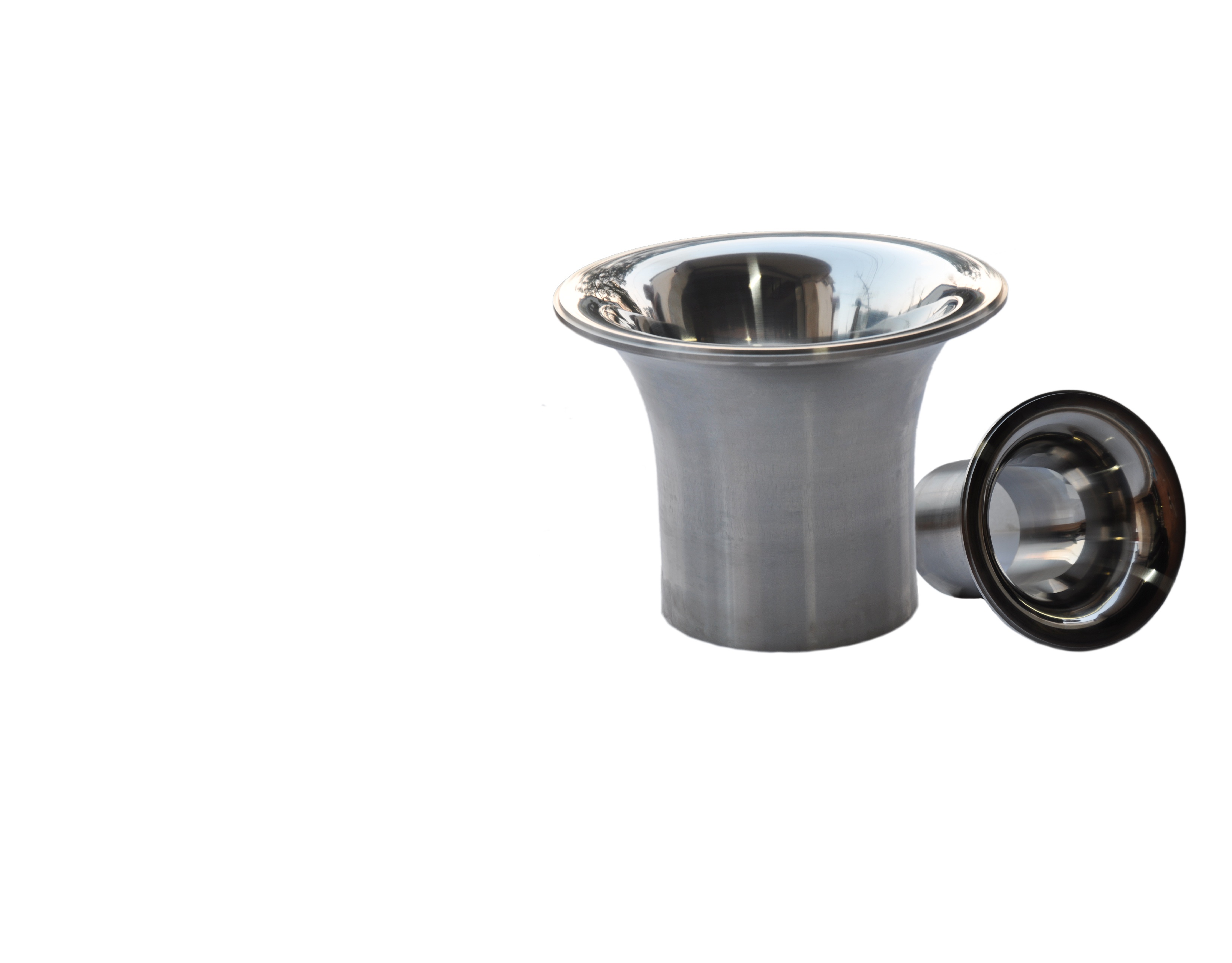
A flow nozzle is a differential pressure primary device with a smoothly rounded convergent inlet leading into a cylindrical throat. The fluid is accelerated through the throat, and the static pressure difference between the upstream side and the throat is used to calculate flow rate. The gradual, contoured inlet gives a more streamlined path than the sharp bore of an orifice plate.
BS EN ISO 5167-3:2020, the UK adoption of ISO 5167-3:2020, covers three standard nozzle types, the ISA 1932 nozzle, the long radius nozzle and the throat-tapped nozzle, together with the Venturi nozzle. They differ in profile and in the position of the pressure tappings. The standard applies to single-phase, subsonic, non-pulsating flow in full circular conduits, in pipes of 50 to 630 mm and at pipe Reynolds numbers of 10 000 and above, and is used together with ISO 5167-1.
Design Basis
A flat inlet face, a convergent section formed by two circular arcs, and a cylindrical throat of length 0.3d, with an optional recess to protect the outlet edge. Corner pressure tappings are used upstream, and the downstream tapping is a corner tapping or a tapping close to the upstream face. Used for 50 to 500 mm pipes with β from 0.3 to 0.8.
A quarter-ellipse convergent inlet and a cylindrical throat of length 0.6d. A high-ratio design covers β of 0.25 to 0.8 and a low-ratio design covers β of 0.2 to 0.5, and either may be used between 0.25 and 0.5. Tappings are at about 1D upstream and 0.5D downstream of the inlet face. Used for 50 to 630 mm pipes with β from 0.2 to 0.8.
An elliptical convergent inlet with the low-pressure signal taken from tappings in the throat itself, rather than from a tapping in the pipe wall. The design draws on the throat-tap nozzle used in ASME PTC 6 performance testing. It is limited to 100 to 630 mm pipes, β of 0.4 to 0.5 and high Reynolds numbers, and has the lowest uncalibrated uncertainty of the three nozzle types.
The same upstream face as the ISA 1932 nozzle, followed by a cylindrical throat and a divergent outlet section with an included angle of 30° or less. The divergent section lowers the pressure loss compared with a similar plain nozzle, and the throat tappings are at least four single tappings joined by an annular chamber or piezometer ring.
Venturi Nozzle page →Each nozzle type may only be used with the standard's coefficient inside the limits below. Outside them, a flow calibration over the full operating Reynolds number range is required.
| Type | Pipe diameter, D | Diameter ratio, β | Reynolds number | Uncertainty of C (uncalibrated) |
|---|---|---|---|---|
| ISA 1932 | 50 – 500 mm | 0.3 – 0.8 | ReD 7×10⁴ – 10⁷ for β < 0.44; 2×10⁴ – 10⁷ for β ≥ 0.44 | 0.8 % for β ≤ 0.6; (2β − 0.4) % for β > 0.6 |
| Long radius | 50 – 630 mm | 0.2 – 0.8 | ReD 10⁴ – 10⁷ | 2.0 % |
| Throat-tapped | 100 – 630 mm | 0.4 – 0.5 | Red 8×10⁵ – 2×10⁷ | 0.7 % |
| Venturi nozzle | 65 – 500 mm, d ≥ 50 mm | 0.316 – 0.775 | ReD 1.5×10⁵ – 2×10⁶ | (1.2 + 1.5β⁴) % |
Pipe roughness limits also apply, such as Ra/D ≤ 3.2 × 10⁻⁴ for long radius nozzles, and Tables 1 and 2 of the standard for ISA 1932 and Venturi nozzles.
The throat is cylindrical, with no diameter differing from the mean by more than 0.05 %, taken from at least four measured diameters. Roughness is Ra ≤ 10⁻⁴ d for ISA 1932, long radius and Venturi nozzles.
Checked against a template. ISA 1932 arcs have radii of about 0.2d and d/3, with an overall length of 0.6041d up to β of 2/3. Long radius and throat-tapped inlets follow elliptical profiles defined by the standard.
Pipe wall tappings are circular, cylindrical over at least 2.5 tapping diameters, flush and burr-free. Diameter is below 0.13D and 13 mm, and upstream and downstream tappings have the same diameter.
Throat-tapped and Venturi nozzles use several tappings joined by an annular chamber, piezometer ring or triple-T arrangement. Annular or interrupted slots are not allowed. Throat tappings are 2 – 7 mm (throat-tapped) or up to 0.04d (Venturi).
ISA 1932 and Venturi nozzles may use carrier rings with annular slots or single tappings. The ring bore is between D and 1.04D, and the ring must not protrude into the pipe.
Single tappings for vapours and liquefied gases are 4 – 10 mm. Annular chamber slots for vapours are 1 – 10 mm wide.
Any material may be used if the geometry is held in service. Throat-tapped and Venturi nozzles are usually metal and must resist erosion and corrosion by the process fluid.
The device is perpendicular to the pipe centreline within 1°, centred within a limit that depends on β, and fixed so that it stays in position and can expand freely. Gaskets must not protrude into the flow.
The rounded, contoured inlet gives a smoother flow path than a sharp-edged orifice bore, and suits clean gas, steam and liquid service.
Uncalibrated uncertainty of C is 0.8 % for ISA 1932 nozzles up to β of 0.6, 0.7 % for throat-tapped nozzles and 2.0 % for long radius nozzles.
ISA 1932 and long radius nozzles are used up to ReD of 10⁷, and the throat-tapped nozzle is characterised up to Red of 2 × 10⁷.
A Venturi nozzle has the same inlet as the ISA 1932 type but a lower pressure loss than a similar plain nozzle.
Expansibility test data exist for air, steam and natural gas, supporting use in compressible service within the standard's limits.
Typically made of metal chosen to resist erosion and corrosion, so the throat keeps its shape in service.
Long radius nozzles cover β from 0.2 to 0.8, allowing sizing for a broad range of flows and differential pressures.
Backed by direct calibration data, with documented methods for flow calculation, uncertainty and installation.
The standard does not cover pipes under 50 mm or over 630 mm, or pipe Reynolds numbers below 10 000.
ISO 5167-3 applies to single-phase, subsonic, non-pulsating flow. Wet gas, two-phase and pulsating flow are outside its scope.
The throat-tapped nozzle is only characterised for β of 0.4 to 0.5, D of 100 to 630 mm and high Reynolds numbers.
Required straight lengths can be long at high β, and the standard notes that the table values are not based on modern data.
Lengths are given in pipe diameters, measured from the upstream face of the device. Column A gives the length for zero additional uncertainty, and column B gives the shorter length for which 0.5 % is added to the uncertainty of C. Three representative values of β are shown, and the full table in the standard covers β from 0.20 to 0.80.
| Fitting | β = 0.30 (A / B) |
β = 0.50 (A / B) |
β = 0.70 (A / B) |
|---|---|---|---|
| Single 90° bend or tee | 10D / 6D | 14D / 7D | 28D / 14D |
| Two or more 90° bends, same plane | 16D / 8D | 20D / 10D | 36D / 18D |
| Two or more 90° bends, different planes | 34D / 17D | 40D / 20D | 62D / 31D |
| Reducer, 2D to D over 1.5D – 3D | 5D / no data | 6D / 5D | 14D / 7D |
| Expander, 0.5D to D over D – 2D | 16D / 8D | 18D / 9D | 30D / 15D |
| Globe valve, fully open | 18D / 9D | 22D / 11D | 32D / 16D |
| Full-bore ball or gate valve, fully open | 12D / 6D | 12D / 6D | 20D / 10D |
| Abrupt symmetrical reduction | 30D / 15D | 30D / 15D | 30D / 15D |
| Fittings downstream of the device | 5D / 2.5D | 6D / 3D | 7D / 3.5D |
A thermometer pocket of diameter up to 0.03D needs 5D / 3D, and one between 0.03D and 0.13D needs 20D / 10D, for all β.
The 2D of pipe next to the nozzle is made with special care, with no diameter more than 0.3 % from the mean. D is the mean of at least twelve measured diameters.
Steps between pipe sections are limited to 0.3 % between 2D and 10D from the nozzle, and to 2 % beyond 10D. Larger steps add 0.2 % uncertainty if within limits.
A conditioner can shorten upstream lengths if it meets ISO 5167-1. A throat-tapped nozzle is compliant with a perforated plate conditioner 16D ± 0.5D upstream of the inlet face and 4D of straight pipe ahead of it.
From an open space or large vessel, at least 30D of pipe is needed. Several fittings in series have further rules, and 2× the table values is recommended for research and calibration work.
A nozzle must be calibrated where lower uncertainty is needed than the standard gives, or where its geometry differs from the standard's. Calibration determines the discharge coefficient of the individual nozzle and its uncertainty.
Calibrate at least over the whole Reynolds number range expected in service, with liquid, gas or both. Use is limited to the calibrated range, and data are not transferable between nozzles.
The facility must give appropriate traceability, with ISO/IEC 17025 as guidance. For throat-tapped nozzles, calibration at a facility operating to ISO/IEC 17025 is required.
Measure at six or more Reynolds numbers, with a maximum above 2.5 × 10⁶ and a minimum between 8 × 10⁵ and 1.5 × 10⁶. A fitted result may then be extended to Red of 2 × 10⁷ within stated limits.
Reports give tabulated and graphical differential pressure, Reynolds number and discharge coefficient. Uncertainties are at 95 % confidence, evaluated by ISO 5168 or ISO/IEC Guide 98-3.
Summarised from BS EN ISO 5167-3:2020. Refer to the full standard for the complete requirements.
Our engineers will select the right nozzle type, ISA 1932, long radius, throat-tapped or Venturi, and deliver a fully sized design to ISO 5167-3, with calibration planned where needed.
Discuss Your Requirements