Background & Motivation
Orifice plates are among the most widely deployed primary flow elements due to their simplicity, low maintenance requirements, and long-term operational reliability. However, the standard single-hole concentric orifice carries two persistent limitations: a substantial permanent pressure loss — which translates directly into energy cost — and a demanding upstream straight-pipe length requirement that increases installation cost and plant footprint.
Multi-hole orifice plates address both of these limitations by distributing the single bore into multiple smaller openings spread across the pipe cross-section. Splitting the bore reduces the severity of the vena contracta, lowering permanent pressure loss. Distributing flow area across the pipe diameter also linearises the velocity profile, making the measurement less sensitive to upstream disturbances and reducing the required straight-pipe run.
While various commercial multi-hole conditioner-meter products exist, independent experimental characterisation of bare multi-hole orifice plates — particularly in the context of generating traceable discharge coefficient data — remains sparse in the open literature. This study was undertaken at Krtyata's R&D calibration laboratory to generate original prototype test data across a range of beta ratios and hole configurations.
Krtyata R&D Flow Calibration Laboratory
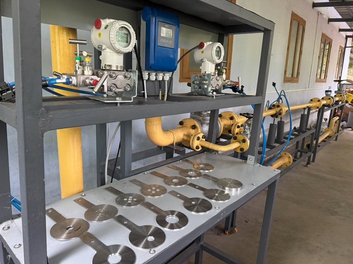
All prototype testing was carried out on Krtyata's water calibration rig using the comparison method, with a reference standard meter of known discharge coefficient placed in series with the device under test. The rig operates at controlled temperature (32 °C), pressure (1.2 bar), and flow rate conditions, with full traceability of all measurements.


Test Programme — Six Prototype Models
Six orifice plate prototypes were designed, machined, and tested at the Krtyata laboratory. The test matrix was structured to compare single-hole and multi-hole configurations at matched beta ratios, enabling direct assessment of the effect of bore distribution on both discharge coefficient and pressure loss.
| Model | Type | Beta Ratio (β) | No. of Holes | Pipe Size | Test Fluid |
|---|---|---|---|---|---|
| Model 1 | Single Hole | 0.40 | 1 | 2″ DN50 | Water |
| Model 2 | Multi-Hole | 0.40 | 9 | 2″ DN50 | Water |
| Model 3 | Single Hole | 0.62 | 1 | 2″ DN50 | Water |
| Model 4 | Multi-Hole | 0.62 | 5 (with centre) | 2″ DN50 | Water |
| Model 5 | Multi-Hole | 0.25 | 5 | 2″ DN50 | Water |
| Model 6 | Multi-Hole | 0.62 | 4 (no centre) | 2″ DN50 | Water |
Prototype Orifice Plate Drawings
Each model was precision-machined in-house. The drawings below show the bore configuration for all six prototypes as tested in the Krtyata calibration laboratory.


