Home › Services › Flow Elements › Venturi Tube
Venturi Tube Design
ISO 5167-4 · As-Cast · Machined · Fabricated · 50 – 1200 mm Lines
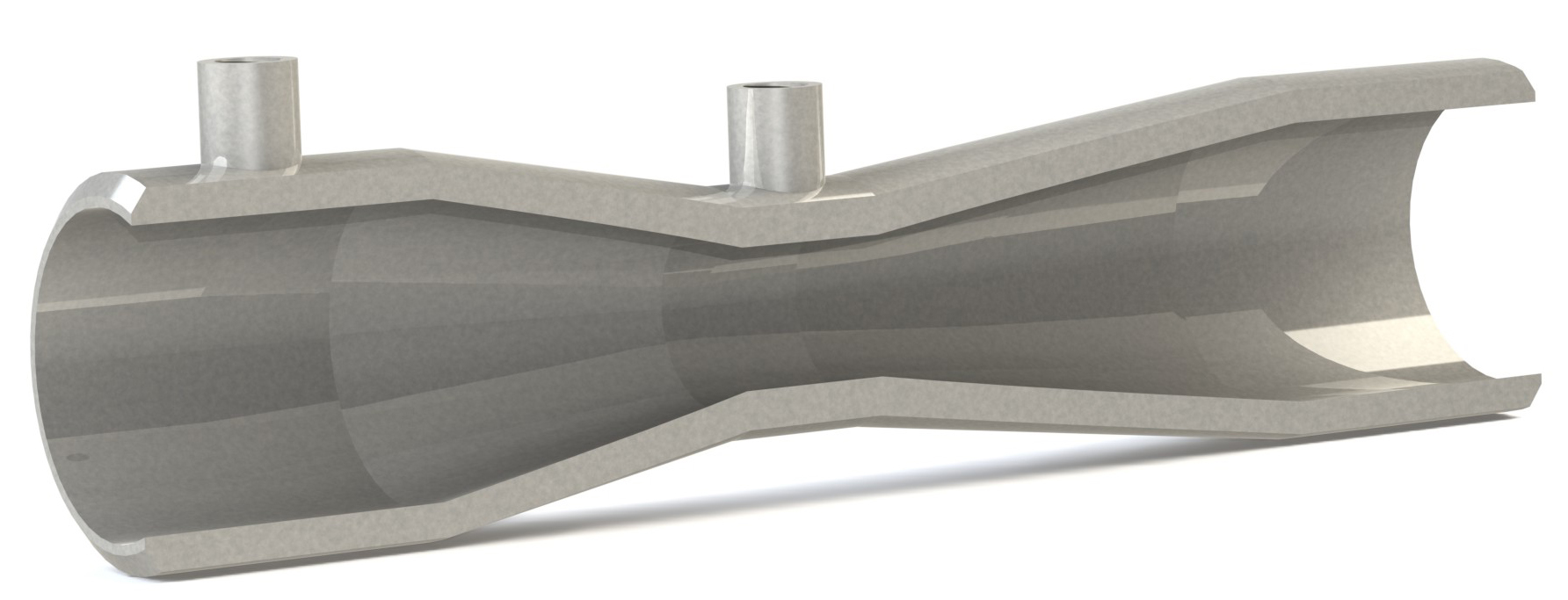
A classical Venturi tube is a primary flow element made up of an entrance cylinder, a conical convergent section, a cylindrical throat and a conical divergent section, also called the diffuser. Differential pressure is measured between a tapping in the entrance cylinder and a tapping in the throat, where the fluid is fastest and the static pressure lowest.
ISO 5167-4:2022 sets out the geometry, installation and operating conditions of the classical Venturi tube for single-phase, subsonic, non-pulsating flow in full circular conduits, and is applied together with ISO 5167-1. Because the diffuser recovers much of the pressure drop, the standard notes that Venturi metering systems have particularly small permanent pressure losses compared with most other flow metering systems. Venturi nozzles, which have a different inlet and are covered by ISO 5167-3, are on the Venturi Nozzle page.
Design Basis
ISO 5167-4 defines three types, distinguished by how the internal surface of the entrance cone is made and how it joins the throat. Each has its own limits of use and discharge coefficient.
Made by sand casting, or another method leaving a similar finish, with a machined throat and rounded junctions between the cylinders and cones. The convergent surface must be free of cracks, fissures and impurities, with Ra below 10⁻⁴ D. Has the lowest uncalibrated uncertainty of the three types.
Cast or fabricated, but with the entrance cylinder, convergent section and throat all machined to the same fine surface finish. Junction radii are small and preferably zero. Suited to smaller line sizes, and its coefficient depends on throat Reynolds number at lower flows.
Rolled sheet iron or other sheet material, welded into cylindrical, convergent and divergent sections. Joins have no curvature other than the weld, and internal welds are flush and kept away from the tappings. Covers the largest pipe sizes, and the throat is machined in smaller sizes.
Within these limits the standard gives a fixed discharge coefficient. Outside them, the Venturi tube must be calibrated over its in-service Reynolds number range. Uncalibrated use is not covered for pipes under 50 mm or over 1200 mm, or for pipe Reynolds numbers below 2 × 10⁵.
| Type | Pipe diameter, D | Diameter ratio, β | Reynolds number, ReD | Discharge coefficient, C | Uncertainty of C (k = 2) |
|---|---|---|---|---|---|
| As cast | 100 – 800 mm | 0.3 – 0.75 | 2×10⁵ – 2×10⁶ | 0.984 | 0.7 % |
| Machined | 50 – 350 mm | 0.4 – 0.75 | 2×10⁵ and above | 0.995 up to 10⁶; 1.000 above 10⁶ | 1 % up to 10⁶; 1.8 % above 10⁶ |
| Fabricated | 200 – 1200 mm | 0.4 – 0.7 | 2×10⁵ – 2×10⁶ | 0.985 | 1.5 % |
Extreme values of D, β and ReD should not be combined, as the uncertainty is likely to increase. Annex B of the standard gives informative guidance outside these limits, but with relatively low reliability, and calibration is recommended instead.
Δp′ and Δp″ are the pressure differences between tappings at least 1D upstream of the inlet flange and 6D downstream of the outlet flange, measured without and with the Venturi tube fitted.
Minimum length D recommended. D is the mean of at least four measured diameters, one near each tapping, and no diameter differs from the mean by more than 0.4 %.
Conical with an included angle of 21° ± 1° for all types, and length of about 2.7(D − d). Its profile deviates by no more than 0.004D at any point.
Cylindrical, length d ± 0.03d, with no diameter more than 0.1 % from the mean. Machined, or equally smooth, with Ra below 10⁻⁴ d and the same finish on the adjacent curvatures.
Conical with an included angle between 7° and 15°, and 7° to 8° recommended for low pressure loss. Its smallest diameter is not less than the throat diameter.
As cast: R₁ about 1.375D, R₂ about 3.625d and R₃ between 5d and 15d. Machined: all radii under 0.25 of the relevant diameter, preferably zero. Fabricated: no curvature other than the weld.
Separate pipe wall tappings, one or more in each plane, which may be joined by an annular chamber, piezometer ring or triple-T arrangement. Single tappings are permitted. Edges are flush and burr-free.
For d of 33.3 mm or more, tappings are 4 – 10 mm, up to 0.1D upstream and 0.13d at the throat. Throat tappings sit 0.5d ± 0.02d from the start of the throat, and upstream tappings about 0.5D from the entrance cylinder junction.
The diffuser may be shortened by about 35 % without significantly changing pressure loss or discharge coefficient. Any material may be used if the geometry is held in service.
The divergent section, or diffuser, is what distinguishes a Venturi tube from an orifice plate or a plain nozzle. Rather than letting the fluid expand abruptly, it widens the flow gradually over a cone whose included angle ISO 5167-4 allows to be anywhere between 7° and 15°, and recommends be kept to 7° to 8° where low pressure loss matters.
The relative pressure loss increases with the divergent angle, and also with surface roughness. As guidance, a 15° diffuser gives a pressure loss roughly 1.2 to 1.9 times that of a 7° diffuser, depending on β, with the larger ratio at smaller β. Pressure loss also falls as β and Reynolds number rise, and levels off above a pipe Reynolds number of about 10⁶.
The trade-off is length against loss. A shallow cone recovers more pressure but makes the Venturi longer, adding material cost, weight and installation length. A steeper cone shortens the device but raises the permanent loss. Because the discharge coefficient is practically unaffected by diffuser length, the angle is chosen on installation length, acceptable permanent loss and cost, and truncation of up to about 35 % of the diffuser length can reduce size further with little penalty.
Schematic only, not to scale
The diffuser recovers most of the throat pressure drop, so permanent loss is typically 5 % to 20 % of Δp, small against most other metering systems.
For the same β, required straight lengths are shorter than for orifice plates, nozzles and Venturi nozzles, because the convergent section smooths flow non-uniformities.
Uncalibrated uncertainty of C is 0.7 % for as-cast, 1.5 % for fabricated, and 1 % to 1.8 % for machined Venturi tubes.
Three construction types together cover pipes from 50 mm up to 1200 mm, with fabricated Venturis available for the largest lines.
Within the limits of use, C is a single value for each type rather than a Reynolds-dependent equation, which simplifies calculation.
Since the 2022 edition, single pipe wall tappings are permitted as well as multiple tappings joined by a piezometer ring or triple-T.
The 2022 edition includes flow calibration requirements, giving a defined route to lower uncertainty or to non-standard designs.
May be made from any material, and fabricated surfaces may be galvanised, provided the specified geometry is held in service.
Uncalibrated use needs pipe Reynolds numbers of at least 2 × 10⁵, and the as-cast and fabricated types are limited to 2 × 10⁶.
ISO 5167-4 covers single-phase, subsonic, non-pulsating flow. Wet gas and two-phase flow are outside its scope.
Straight lengths are shorter, but the Venturi itself, with its convergent, throat and diffuser, adds length that must be included in the installation.
Machined Venturis are limited to 350 mm, as-cast to 100 – 800 mm, and fabricated to 200 – 1200 mm, so the choice of type follows the line size.
Lengths are in pipe diameters, measured from the end of the curved part of the nearest bend, or the end of the curved or conical part of a reducer or expander, to the upstream tapping plane. Column A is the length for zero additional uncertainty, and column B is the shorter length for which 0.5 % is added to the uncertainty of C. Three representative values of β are shown, and the full table in the standard covers β from 0.30 to 0.75.
| Upstream fitting | β = 0.30 (A / B) |
β = 0.50 (A / B) |
β = 0.70 (A / B) |
|---|---|---|---|
| Single 90° bend | 8D / 3D | 9D / 3D | 14D / 3D |
| Two or more 90° bends, same or different planes | 8D / 3D | 10D / 3D | 18D / 3D |
| Reducer, 1.33D to D over 2.3D | 4D / no data | 4D / no data | 4D / no data |
| Expander, 0.67D to D over 2.5D | 4D / no data | 5D / 4D | 7D / 5D |
| Reducer, 3D to D over 3.5D | 2.5D / no data | 5.5D / 2.5D | 10.5D / 2.5D |
| Expander, 0.75D to D over D | 2.5D / no data | 2.5D / no data | 5.5D / 3.5D |
| Full-bore ball or gate valve, fully open | 2.5D / no data | 3.5D / 2.5D | 5.5D / 3.5D |
Bend radius must be at least the pipe diameter. Fittings, or densitometer pockets, at least four throat diameters downstream of the throat tapping plane do not affect accuracy.
The upstream pipe must be cylindrical for at least 2.5D before the upstream tapping, with no diameter more than 2 % from the mean and its mean within 1 % of D. Roughness within 3D of the tapping is Ra/D ≤ 3.2 × 10⁻⁴.
Centreline offset from the upstream pipe is under 0.005D and angular misalignment under 1°. Matched-bore flanges, dowels or self-centring gaskets help achieve this.
Temperature pockets are up to 0.13D in diameter and at least 4D upstream of the tapping plane. The downstream pipe diameter is not less than 90 % of the diffuser outlet diameter.
Fittings in series have extra spacing rules, and doubling the table values is recommended for research and calibration work. Flow conditioners may be used if they meet ISO 5167-1.
A Venturi tube must be calibrated where lower uncertainty is needed than the standard gives, or where its geometry differs from the standard's. Calibration determines the discharge coefficient of the individual tube and its uncertainty.
Calibrate at least over the whole Reynolds number range expected in service, with liquid, gas or both. Use is limited to the calibrated range and extrapolation is not permitted.
The facility must give appropriate traceability for the application, with ISO/IEC 17025 as guidance. For gas service, a water calibration at ambient temperature may not reach the required Reynolds range.
Install with at least the Clause 6 straight lengths. With a flow conditioner, calibrate a package of 4D upstream of it, the conditioner, the Venturi and 2D downstream. Replicate service piping if it differs significantly.
Reports give differential pressure, Reynolds number and discharge coefficient. Calibration data are not transferable between tubes, and each set of tappings is a separate meter. Uncertainties are at k = 2, evaluated by ISO 5168 or ISO/IEC Guide 98-3.
Summarised from ISO 5167-4:2022. Refer to the full standard for the complete requirements.
Our engineers will select the right construction type, as-cast, machined or fabricated, and set the divergent angle for your pressure loss and installation length, to ISO 5167-4.
Discuss Your Requirements