Home › Services › Flow Elements › Cone Meter
Cone Meter Design
ISO 5167-5 · Short Straight-Length · Self-Conditioning · 50 – 500 mm Lines
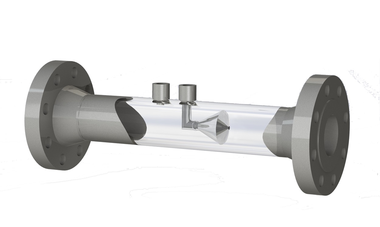
A cone meter is a differential pressure flow element with a cone-shaped restriction held concentrically in the centre of the pipe, its nose pointing upstream. The fluid is forced into the annular gap between the cone and the pipe wall, which raises its velocity and lowers its pressure. One or more upstream tappings in the pipe wall sense the approach pressure, while the low-pressure signal is taken from a tapping in the back face of the cone, carried through the cone and up the support bar to the transmitter.
ISO 5167-5:2022 defines the geometry, installation and operating conditions of this design for single-phase, subsonic, non-pulsating flow in a full circular conduit, and is applied together with ISO 5167-1. The cone also reshapes a distorted approach velocity profile, and the standard notes that cone meters are relatively insensitive to common upstream disturbances, which is why they can be installed with short straight lengths.
The diameter ratio is defined by the cone's area at its widest edge, the beta edge: β = √(1 − dc²/D²). A larger cone therefore gives a smaller β.
Design Basis
An uncalibrated cone meter may use the coefficient given in ISO 5167-5 only inside the limits below. Outside them, including any meter with β above 0.75, the discharge coefficient must be established by flow calibration over the full Reynolds number range of operation.
| Pipe internal diameter, D | 50 mm ≤ D ≤ 500 mm |
|---|---|
| Diameter ratio, β | 0.45 ≤ β ≤ 0.75 |
| Pipe Reynolds number, ReD | 8 × 10⁴ ≤ ReD ≤ 1.2 × 10⁷ |
| Pipe roughness, Ra | Less than 10⁻³ D |
| Cone surface roughness, Ra | Less than 5 × 10⁻⁴ dc |
| Flow condition | Single-phase, subsonic, non-pulsating, pipe running full |
Extreme values of D, β and ReD should not be combined, as the uncertainty may increase. Meters with β below 0.45 are not normally manufactured.
The standard fixes the main dimensions of the cone assembly and its tappings so that the published coefficient applies. The key requirements are summarised here.
A bifrustum of two truncated cones joined at the beta edge. The upstream frustum angle is 22.5° ± 5° and the downstream angle is 64° ± 2.5°. The beta edge is not sharp, with a radius below 0.2 mm or 0.0005 dc, whichever is smaller.
Cone diameter is measured at least four times at the beta edge, and no diameter may differ from the mean by more than 0.1 %. The measured internal pipe diameter, not the nominal, is used in the calculation.
Cone-to-wall gaps are checked at the beta edge and at the nose, each within 5 % of their mean. Angular deviation is within 2° and lateral offset within 0.01D.
The support structure presents as small a restriction as practical. Gussets are recommended where vibration is significant, and fabricated cones need pressure relief vent holes through the downstream face.
A pipe wall tapping of 4 – 10 mm, never more than 0.1D, with a flush, burr-free edge and its centreline meeting the pipe centreline. More than one upstream tapping is permitted.
A cylindrical hole in the back face of the cone, concentric with it, of 0.1 to 0.2 times dc, connected through the support bar to the transmitter.
The distance L between the upstream tapping plane and the downstream tapping is at least 50 mm and at most 2D.
The nose may be flat, pointed, curved, or formed from an elbow, and sits downstream of the upstream tapping plane. It should be as short as practicable.
Only 3D to 6D of upstream pipe is needed after a bend, depending on β, and fittings 2D downstream add no error. Flow conditioners are generally not required.
The cone reshapes the approach profile, so common disturbances such as bends and expanders have a modest effect on performance.
The uncalibrated coefficient covers ReD from 8 × 10⁴ to 1.2 × 10⁷, and a flow calibration extends use beyond these limits.
With a Clause 7 calibration, discharge coefficient uncertainty becomes comparable to that of the other ISO 5167 devices.
Suited to existing piping where space for long straight runs is limited, without major pipework redesign.
Covered by ISO 5167-5, giving a documented method for flow calculation, uncertainty and installation.
The orientation of the cone meter is irrelevant, which simplifies installation in horizontal, vertical or inclined lines.
May be made from any material, provided the specified geometry is held in service.
An uncalibrated meter carries a 5 % coefficient uncertainty, relatively high compared with other ISO 5167 devices, so calibration is recommended for higher accuracy.
Uncalibrated use is limited to 50 – 500 mm lines with β of 0.45 – 0.75. Any meter with β above 0.75 must be calibrated.
ISO 5167 covers single-phase flow. Wet gas or multiphase service lies outside the standard and needs dedicated calibration or correlations.
Results apply to the individual meter tested, cannot be extrapolated, and each set of tappings is treated as a separate meter.
Upstream lengths are measured from the end of the curved part of the nearest bend, or the end of the curved or conical part of a reducer or expander, to the centreline of the upstream tapping.
| Upstream fitting | β 0.45 to < 0.6 | β 0.6 to 0.75 |
|---|---|---|
| Single 90° bend | 3D | 6D |
| Two 90° bends, perpendicular planes | 3D | 6D |
| Concentric expander (0.75D to D) | 3D upstream adds up to 0.5 % to flow rate uncertainty | |
| Partially closed valve | Not within 10D upstream | |
| Fully open full-bore isolation valve | No additional error | |
A concentric reducer is a less significant disturber than an expander.
Fittings at least 2D downstream of the beta edge introduce no additional error.
The pipe must be cylindrical for at least 6D upstream and 2D downstream, with no diameter more than 2 % from the mean. Roughness stays below 10⁻³ D over 5D upstream and 2D downstream.
Best located upstream of the straight-length requirement. If placed downstream, it sits 5D to 15D from the beta edge, and never within 5D. A thermowell inside the straight length or ahead of the nose means the meter must be calibrated with it fitted.
Where lower uncertainty is needed, or the design differs from the standard's geometry, the standard calls for the meter to be flow calibrated. Calibration determines the discharge coefficient of the individual meter and its uncertainty.
Calibrate at least over the entire Reynolds number range expected in service, using liquid, gas, or both in separate tests. Extrapolation is not permitted.
The facility must give appropriate traceability for the application, with ISO/IEC 17025 as guidance on what is suitable.
At least 6D of upstream and 2D of downstream straight pipe are used, with no flow conditioner. If service piping differs significantly, or β exceeds 0.75, it should be replicated.
Reports give differential pressure, Reynolds number and discharge coefficient, with uncertainties at k = 2 evaluated by ISO 5168 or ISO/IEC Guide 98-3.
Summarised from ISO 5167-5:2022. Refer to the full standard for the complete requirements.
Our engineers will size a cone meter to ISO 5167-5 for your process conditions and straight-length constraints, and plan the calibration if needed.
Discuss Your Requirements